STORM WATER PIPE SIZING CALCULATOR FOR BUILDING SITES
Note:
This program is based on the Australian Plumbing Code AS/NZS 3500.3:2021 and as such it is a very simplified method of calculating pipe sizes. It takes no account of losses such as entry and exit losses, and losses due to bends and fittings (it only calculates pipeline friction losses).
The rainfall intensity used is 1:20 (ARI 20, AEP 5%), this means it is suitable for connecting the Down pipes from eaves gutters. However the code allows site drainage to be calculated from ARI 1 to ARI 20, depending on the likelyhood of damage from overflow.
Therefore you are free to enter any intensity you desire.
All overflowing should be calculated for ARI 100 and carried away from the building without damage. The top water level of any overflowing should be at least 300mm below the floor level or damp course of any adjacent building.
Losses due to fittings etc are assumed to be compensated for, by allowing water to rise up a bit into the down pipe or catch pit. These losses are usually minor as the velocity is regulated as explained below, and the nearest available pipe size is usually bigger than the theoretical size required, resulting in the pipes not flowing full.
Also if the theoretical pipe diameter is greater than 4mm of an available pipe diameter, the next higher available pipe size is shown. This is to allow for the slight discrepancies when dealing with "nominal" diameters.(DN)
The velocity shown, is calculated on this next higher pipe size, flowing full at the design flow, as per code requirement.
Please note that this is not necessarily the true velocity. It is a simple rule of thumb method used by the Plumbing Code as a means to reduce possible losses. The code requires this velocity to be kept below 2m/s. (Pipeline losses are dependent on the velocity). It is probably not that important for a single pipe, but when you start joining pipes together these (uncalculated) losses can add up. Hence the 2m/s requirement.
Some explanation, because we have selected the next larger pipe size than what is 'theoretically required', the pipe is unlikely to be flowing full, so to be strictly correct the 'flowing part full calculations' should be used if designing Municipal systems. Some brief info on 'part full velocity' is shown here.
If you wish to join a number of pipes together This calculator makes it easy.
GRADE, AND "CHARGED" PIPES
The term "charged" pipes in this context means pipes flowing full, under slight head, or pipes that stay full when the flow has stopped. For example pipes from a down pipe that go underground and up again to a tank, pipes that enter below the water level in a dam, creek or river etc. Or pipes where the water level is allowed to build up substantially in a down pipe to give it more head, and hence increase the flow.
If designing a pipe under these conditions the "Available grade" to enter in the program is the "hydraulic" grade, not the actual grade of the pipe.
Read more about this here.
Although the program will allow you to enter any grade, all Codes stipulate minimum allowable grades, and sometimes maximum allowable grades.
Minimum allowable in the Australian Plumbing Code AS/NZS 3500 can be found here.
PIPE TYPES
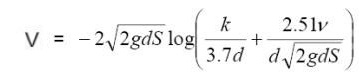
The Formula used is Colebrook-White (k=0.015) as per the Australian Plumbing Code.
This is suitable for smooth pipes like PVC, copper, stainless steel etc.
For other pipe types, you could activate the extra features, allowing you to enter any resistance and runoff coefficient.
Roughness Coefficients Used
RAINFALL
If using the drop down town list for rainfall intensity, the storm recurrence interval is 20 years. Duration is 5mins for Australia. (NZ towns ARI 10 years, duration 10mins)
This is the intensity for eaves gutters.
If using box gutters, pervious areas, or areas that will not cause any damage if overflowing, the allowable intensity can be different.
If you wish to take these factors into account this program may be more suitable.
However by using the extra features above, these requirements can be adjusted by calculating the design flow elsewhere, then adding in the box.
COEFFICIENT OF RUNOFF
The coefficient of runoff is taken a 1. That is, 100% runoff, as in a roof.
If using the program for a different coefficient of runoff, multiply the catchment area by that coefficient before entering it in the calculator. For example with a catchment area of 100sqm and a Coefficient of runoff of 0.6 (60%), the area to enter into the program is 100 x 0.6 = 60 sqm.
Alternatively save yourself the agro and activate the extra features
Storm water design for Municipal systems is based on the Hydraulic Grade line, which takes into account all losses in the system. e.g. through access chambers, junctions, catch pits etc. And also allows for pipes discharging below water level.
To learn about this, and storm water design principles in general click here..
However this level of detail is not required for single straight pipes, and is not required under the Australian Plumbing Code. The code makes allowances for losses by other means and a slightly different approach.
This method is explained more fully in the 'Notes and Instructions' on using the multiple pipeline calculator.
How to Enter a Known Flow
What if you have many catchments of varying coefficients of runoff and intensities, all draining to this pipe?
In this case you must calculate the total runoff by adding the runoff from each catchment separately.
The runoff equation is Q = C*I*A/3600. Where Q is L/s: I is mm/hr; A is sqm.
To use this in the program without paying me any money, make the Area equal 3600, when divided by 3600 will cancel out, leaving the intensity equal to the required flow. (C = 1).
For example, say your known flow is 20 L/s, enter 3600 as the area, set the location to "I prefer to enter a know Intensity", and enter 20 as the intensity. the flow will be calculated to be 20 L/s.
Or you could activate the extra features and have the program do it for you.
This will give me half a six pack and bus fare home. Which will be good.
Entering a known flow, does not require any rainfall, catchment, or coefficient of runoff data. Any such data in these fields is ignored.
HOW DOES THIS AFFECT DOWNPIPES
What if we use this method to size a pipe from a down pipe, and find that the resulting pipe is smaller than the downpipe itself. (Assuming the Downpipe was sized in the Downpipe calculator)
A Down pipe size is more dependent on the perimeter of the pipe (circular weir, or orifice) at the entrance, than the cross sectional area. And as such does not flow full. Whereas the underground pipe maybe flowing full, thereby resulting in a smaller pipe.
Now it is very bad practice to reduce a pipe size downstream. Besides which it is against all codes and requirements and laws. It is also a potential blockage problem.
So, we can put in more DP's to reduce their size, or we can flatten the grade of the underground pipe to increase it's size, or we can enlarge the Downpipe at the entrance to the diameter required by the downpipe calculator, thereby providing a "Funnel" into the vertical pipe. Or we could just enlarge the underground pipe and say nothing to anybody.
Note: Don't use this to design syphonic systems though, as a syphonic systems need special fittings to get it started, and also to remove entrapped air.
What if ?
What if the storm intensity is greater than the pipe was designed for? or what if the pipe gets blocked?
Then, if there is a risk of serious damage, you may wish to design an overland flow path.
More Instructions
Copyright Ken Sutherland 2016This program is based on the Australian Plumbing Code AS/NZS 3500.3:2021 and as such it is a very simplified method of calculating pipe sizes. It takes no account of losses such as entry and exit losses, and losses due to bends and fittings (it only calculates pipeline friction losses).
The rainfall intensity used is 1:20 (ARI 20, AEP 5%), this means it is suitable for connecting the Down pipes from eaves gutters. However the code allows site drainage to be calculated from ARI 1 to ARI 20, depending on the likelyhood of damage from overflow.
Therefore you are free to enter any intensity you desire.
All overflowing should be calculated for ARI 100 and carried away from the building without damage. The top water level of any overflowing should be at least 300mm below the floor level or damp course of any adjacent building.
Losses due to fittings etc are assumed to be compensated for, by allowing water to rise up a bit into the down pipe or catch pit. These losses are usually minor as the velocity is regulated as explained below, and the nearest available pipe size is usually bigger than the theoretical size required, resulting in the pipes not flowing full.
Also if the theoretical pipe diameter is greater than 4mm of an available pipe diameter, the next higher available pipe size is shown. This is to allow for the slight discrepancies when dealing with "nominal" diameters.(DN)
The velocity shown, is calculated on this next higher pipe size, flowing full at the design flow, as per code requirement.
Please note that this is not necessarily the true velocity. It is a simple rule of thumb method used by the Plumbing Code as a means to reduce possible losses. The code requires this velocity to be kept below 2m/s. (Pipeline losses are dependent on the velocity). It is probably not that important for a single pipe, but when you start joining pipes together these (uncalculated) losses can add up. Hence the 2m/s requirement.
Some explanation, because we have selected the next larger pipe size than what is 'theoretically required', the pipe is unlikely to be flowing full, so to be strictly correct the 'flowing part full calculations' should be used if designing Municipal systems. Some brief info on 'part full velocity' is shown here.
If you wish to join a number of pipes together This calculator makes it easy.
GRADE, AND "CHARGED" PIPES
The term "charged" pipes in this context means pipes flowing full, under slight head, or pipes that stay full when the flow has stopped. For example pipes from a down pipe that go underground and up again to a tank, pipes that enter below the water level in a dam, creek or river etc. Or pipes where the water level is allowed to build up substantially in a down pipe to give it more head, and hence increase the flow.
If designing a pipe under these conditions the "Available grade" to enter in the program is the "hydraulic" grade, not the actual grade of the pipe.
Read more about this here.
Although the program will allow you to enter any grade, all Codes stipulate minimum allowable grades, and sometimes maximum allowable grades.
Minimum allowable in the Australian Plumbing Code AS/NZS 3500 can be found here.
PIPE TYPES
The Formula used is Colebrook-White (k=0.015) as per the Australian Plumbing Code.
This is suitable for smooth pipes like PVC, copper, stainless steel etc.
For other pipe types, you could activate the extra features, allowing you to enter any resistance and runoff coefficient.
Roughness Coefficients Used
| Pipe Material | k |
|---|---|
| Smooth bore pipelines, Plastic, Copper, stainless steel etc | 0.015 |
| Fibre Reinforced Concrete (FRC) | 0.15 |
| Cast Iron, Ductile Iron, Galvanised Steel, Vitrified Clay (VC), Precast Concrete etc | 0.6 |
| Corrugated Aluminium and Steel | 3 |
RAINFALL
If using the drop down town list for rainfall intensity, the storm recurrence interval is 20 years. Duration is 5mins for Australia. (NZ towns ARI 10 years, duration 10mins)
This is the intensity for eaves gutters.
If using box gutters, pervious areas, or areas that will not cause any damage if overflowing, the allowable intensity can be different.
If you wish to take these factors into account this program may be more suitable.
However by using the extra features above, these requirements can be adjusted by calculating the design flow elsewhere, then adding in the box.
COEFFICIENT OF RUNOFF
The coefficient of runoff is taken a 1. That is, 100% runoff, as in a roof.
If using the program for a different coefficient of runoff, multiply the catchment area by that coefficient before entering it in the calculator. For example with a catchment area of 100sqm and a Coefficient of runoff of 0.6 (60%), the area to enter into the program is 100 x 0.6 = 60 sqm.
Alternatively save yourself the agro and activate the extra features
Storm water design for Municipal systems is based on the Hydraulic Grade line, which takes into account all losses in the system. e.g. through access chambers, junctions, catch pits etc. And also allows for pipes discharging below water level.
To learn about this, and storm water design principles in general click here..
However this level of detail is not required for single straight pipes, and is not required under the Australian Plumbing Code. The code makes allowances for losses by other means and a slightly different approach.
This method is explained more fully in the 'Notes and Instructions' on using the multiple pipeline calculator.
How to Enter a Known Flow
What if you have many catchments of varying coefficients of runoff and intensities, all draining to this pipe?
In this case you must calculate the total runoff by adding the runoff from each catchment separately.
The runoff equation is Q = C*I*A/3600. Where Q is L/s: I is mm/hr; A is sqm.
To use this in the program without paying me any money, make the Area equal 3600, when divided by 3600 will cancel out, leaving the intensity equal to the required flow. (C = 1).
For example, say your known flow is 20 L/s, enter 3600 as the area, set the location to "I prefer to enter a know Intensity", and enter 20 as the intensity. the flow will be calculated to be 20 L/s.
Or you could activate the extra features and have the program do it for you.
This will give me half a six pack and bus fare home. Which will be good.
Entering a known flow, does not require any rainfall, catchment, or coefficient of runoff data. Any such data in these fields is ignored.
HOW DOES THIS AFFECT DOWNPIPES
What if we use this method to size a pipe from a down pipe, and find that the resulting pipe is smaller than the downpipe itself. (Assuming the Downpipe was sized in the Downpipe calculator)
A Down pipe size is more dependent on the perimeter of the pipe (circular weir, or orifice) at the entrance, than the cross sectional area. And as such does not flow full. Whereas the underground pipe maybe flowing full, thereby resulting in a smaller pipe.
Now it is very bad practice to reduce a pipe size downstream. Besides which it is against all codes and requirements and laws. It is also a potential blockage problem.
So, we can put in more DP's to reduce their size, or we can flatten the grade of the underground pipe to increase it's size, or we can enlarge the Downpipe at the entrance to the diameter required by the downpipe calculator, thereby providing a "Funnel" into the vertical pipe. Or we could just enlarge the underground pipe and say nothing to anybody.
Note: Don't use this to design syphonic systems though, as a syphonic systems need special fittings to get it started, and also to remove entrapped air.
What if ?
What if the storm intensity is greater than the pipe was designed for? or what if the pipe gets blocked?
Then, if there is a risk of serious damage, you may wish to design an overland flow path.
More Instructions
Contact
If you find that the programs useful, please feel free to buy me a beer.