To AS/NZS 3500.3:2021 "Stormwater Drainage Acceptable Solutions".
(This program will calculate the size of eaves gutters, and the number of downpipes required for roof drainage)
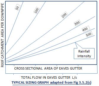
The Code Figure 3.5.2(B) or (C) relate gutter cross sectional area to the Litres/sec that the gutter area can carry.
Knowing the rainfall Intensity, the "effective" catchment area for that gutter cross section can be read from the graph.
(The effective catchment area takes into account the roof slope, and any vertical faces).
Dividing the total "effective" roof catchment area by the catchment area for the gutter selected, will give the number of downpipes required. This is not normally a whole number, so it is rounded up to the nearest whole number. Dividing the total flow from the roof by the number of downpipes will give the flow per downpipe.
Now the only way to find the required downpipe size is from Table 3.5.2, which requires knowing the gutter size.
But because the number of downpipe's has been increased to a whole number, the flow in each will be slightly less than the gutters available capacity. In other words the gutter will not be flowing full with the chosen roof area, and number of downpipes required.
As an explanation, Using more downpipes will result in a smaller flow per downpipe and also in the gutter, as the flow in the gutter and downpipe are identical.
Using less downpipes produces a larger flow in each downpipe and gutter. This larger flow will be greater than the chosen gutter can handle.
Anyway no sense selecting a downpipe size to suit a gutter that doesn't flow full at the design flow. So, going back to the graph 3.5.2(B) or (C) with this new flow will give a new gutter size that is slightly smaller than the original selected gutter.
Then from Table 3.5.2 the downpipe size is found that relates to the smaller gutter area, and hence the actual flow.
Use the program "Working back the other way" to see how this works in real life.
It is the designers responsibility to find the best compromise between downpipe size, the number required, and the gutter size.
The Free version
This program is designed for a quick overview of all sizing possibilities, it works back the other way from the Code version. That is, selecting the downpipe size first, then finding the number required, and the gutter area that is required to service that downpipe. This gives the perfect match between gutter and down pipe. The gutter can be folded to suit, or the nearest (greater) standard size can be selected.
The building designer can see all the "what ifs" at a glance. Large buildings may be limited in the number of downpipes that can be fitted due to column spacing, Architectural features, or other aesthetic considerations. Therefore the number of downpipes that will fit, may be the deciding parameter.
The More Down Pipes function
In Table 3.5.2, downpipes are sized on gutter area. Sizes jump from one size to the next available size. For instance a 125 diameter downpipe jumps to 150 dia. there are no sizes in between.
So, if using the More Down Pipes function, all the in-between sizes are calculated.
Therefore the size shown in the printout will be shown as "interpolated" from table 3.5.2.
The 'available' size from the table is also shown.
Downpipes:
Check the number of downpipe's required, if the figure is say 0.1, then that downpipe is only 1/10 full.
You will be guilty of gross over design if you use this. A smaller downpipe should be used.
If you have the case of say, 3.25 number * 150 dia downpipe's required, then you may choose to split the catchments to have 3*150 & 1*100 dia downpipe's. However, it is normally better to keep all downpipe's the same size and accept 4 * 150 downpipe's.
Downpipe (Down Pipe) Spacing:
Although not stated in the plumbing code, the National Construction Code requires that a downpipe collect no more than 12m of gutter.
There are two reasons for this, although only one is stated.
1. The formula to derive the depth in a spatially varied flow channel, or to derive the depth of a back water curve resulting from flow over a weir or other obstruction, usually has a length component. Especially if the gutter is rather flat. The water level can build up the further one goes back from the outlet.
So to make everything work out with the Code formulas, the length of eaves gutters draining to a downpipe should be restricted to gutters shorter than 12m.
2. This would also apply to straight runs of gutter to limit the expansion. Although it is conceivable to have a 24m length of gutter with a down pipe at each end, thereby limiting the gutter run to each downpipe to 12m, and also satisfying the Code requirement of 12m/DP, a straight run of gutter this long would fall foul of table 4.3.2 (AS/NZS 3500.3:2021) rough guide here.
This would require an expansion joint in the middle.
Roof design:
If using the number of downpipes calculated above, try to have approximately equal catchment areas draining to each down pipe, with high points approx midway between downpipes, and at the end of valley gutters. However locate downpipes as close as possible to valley gutters, with preferably no bends between the valley gutter and the downpipe.
Don't forget, if there are no stop ends in the gutter, water may flow a little between catchments. i.e. if one downpipe is overloaded, excess water may continue to the next downpipe.
If it is not possible to have equal catchments, and a catchment area is much larger than the others, then run the program again for just that larger catchment, it may require an extra downpipe.
Any size, or shape eaves gutter may be used, as long as the cross sectional area is equal to, or greater than, the size calculated. However some shapes are more efficient than others. For instance a semicircular eaves gutter is more efficient than a rectangular one.
For rectangular eaves gutters, the most efficient shape is when the width is approximately twice the depth. So try to select a gutter that is close to this, as this is what the plumbing code expects.
The number of downpipes required is the theoretical number required. This is not always a whole number. So the number used in the eaves gutter area calculation, is the theoretical number rounded up to the next whole number.
Also, the Code only refers to the "Nominal Diameter". The actual Internal diameter may be more or less, depending on the material and pipe class chosen.
When designing pipework, we must always use the internal pipe diameter in all calculations, however some suppliers quote stormwater pipes as the Outside Diameter, so a 150 (nominal) pipe dia shown in the calculator is taken as referring to a 160mm 'outside' dia (PVC) storm water pipe in the catalogue. This pipe is about 154mm internal diameter.
This is how 'nominal' diameters work. It defines any pipe that is 'around about' that diameter.
If you want to be strictly correct, find the exact internal diameter of your chosen material and pipe size, and enter this in the 'extra features' function. This may or may not give a different number required. For instance if the theoretical number required is 3.01 you will need 4 down pipes. However with a pipe a few mm larger this may come down to 3. It works in reverse too, if your chosen pipe is a few mm smaller that the nominal diameter, you may need an extra downpipe.
Minimum Roof Slope :
The recommended minimum roof slope for corrugated metal roofs is 5 degrees. For some wide trough, long span metal roofing the minimum slope is 1.5 degrees.
Some Theory :
The time of concentration is the time it takes water to travel from the furthermost point in the catchment to the point under investigation. To generate peak flow from a catchment, a storm must last at least this long. Now the longer a storm lasts, the less is the average intensity. eg a storm may bucket down for 5 mins, but is not likely to keep up such an intensity for hours.
The flow of water in a down pipe is restricted by the size of the entry (ie the entry diameter, throat, or orifice.) Water starts to enter a downpipe as though it was flowing over a weir into the mouth of the downpipe. The weir formula is used to calculate the downpipe size.
As the flow builds up, the water level over this weir increases until the entire mouth of the downpipe is submerged, just like your bath tub when you pull the plug. The downpipe entry now acts like an orifice, and the orifice formula is used to calculate the downpipe size.
The greater the depth of water over the down pipe, the more water can be forced through this entry orifice, or over the entry edge (weir). This is why we have a rain water head over some downpipes, to increase the depth of water over the entry and hence force more water into the downpipe.
Note: down pipes do not flow full (except in syphonic systems) so pipe flowing full formulas do not work.
Another way to increase the downpipe capacity, is to increase the throat diameter by having a conical entrance
to the downpipe. Hence increasing the length of the entry weir.
However you should approach a consultant on this as it is not always applicable.
A down pipe designed to the code does not flow anywhere near full, it is the entry orifice/weir that limits the flow.
If you want to investigate this further, check out the notes on the pipe size calculator
Charged downpipes.
and pipes flowing to tanks, or discharging under water.
A "charged" downpipe is one that flows full, or stays full because of a "U" shape.
AS3500 does not take into account the location of the downpipe along the gutter, nor does it adjust the formula for bends in the gutter.
This can make a big difference. The code only allows for the worst possible case. This makes it ideal for residential buildings with many turns and bends in the roof. However for projects with long straight roofs (Large industrial Sheds) it would be conservative (ie an overdesign).
For these projects, the CSIRO have produced formulas that take into account the location of down pipes and bends along the gutter. The relevant document is here Roof Drainage by K G Martin
I have used these formulas to create another calculator here. Cost savings of up to 20% can be achieved.
I would also be interested in any modifications, or suggestions that you would
like incorporated.
If you need more info, or you would like other areas of Australia, or New
Zealand, added to the list,
please contact me.