STORM WATER NETWORK PIPE SIZING CALCULATOR FOR BUILDING SITES
This version of the pipe network calculator is limited to only 4 catchment Areas.
To activate the full version you have two other options:-
Purchase activation for all the extra features on this site Activate now
or activate a 2 day free trial of all the extra features on this site. Activate free trial
To activate the full version you have two other options:-
Purchase activation for all the extra features on this site Activate now
or activate a 2 day free trial of all the extra features on this site. Activate free trial
Legend
Some text in red Italic, means click for further info.
Indicates a calculated field. User cannot change.
Indicates a calculated (or assumed, or default) field. User can modify.
Indicates a diameter has been increased to reduce the velocity to the max Code allowable.
Indicates the Final Outlet.
Indicates a User (or program) changed value, where other factors have affected the default value.
Indicates a Problem. click for details.
Indicates a downpipe click for info
Indicates a given Flow from a DP click for info
Indicates a given PipeFlow from another network click for info
Indicates a Pit accepting surface runoff. (found by the program. Optionally named by the user)
Indicates a user defined access point,(MH, inspection opening, etc) not accepting surface runoff,
(The first character is alpha, and the last character is nuneric.)
To Calculate: Press the 'Calculate Pipe Size' button. This can be done on any amount of input data.
Important Naming Conventions Example.
1. All catchments to be given only numbers. eg 1,2,3,4,...etc.
2. All junctions, or change of grade, (nodes) to be given only letters. eg A, B, AA, AB,.... etc
3. All access or junction pits, or catch pits, should be given a name, starting with a letter, and ending with a number. eg. MH1, GP1, PIT1,..etc. Pits receiving surface runoff will be found by the program. However it is still necessary to give all water entry structures, junction pits, and access chambers, a name like this. This is particularly important if calculating invert levels, as the code requires a fall of 20mm through pits
WARNING:
These results are for the perfect site, and should be treated as a first step. There are many other things that should be considered before
the final design. For instance:-
NOTE: - Are there any clashes with other pipes or obstacles, requiring the pipes to be raised or lowered?.
- If the pipes won't drain because the final IL is too low, it may be necessary to have a "charged" pipe somewhere.
- If there are many pipes entering a pit, (especially if they are not at right angles to each other) the pit size should be checked to see if all the pipes will fit.
- Sometimes the required cover can be reduced by using a steel pipe, or encasing in concrete.
- There may be requirements for Gross Pollutant traps, or On Site Detention (OSD) ponds.
- This program is designed to give the shallowest pipe system possible. Sometimes if the pipes will still drain, it may be more economical to steepen some pipe sections to give a smaller pipe diameter. The economics of this however, depends on the length of the pipe involved, and the increase in depth/excavation.
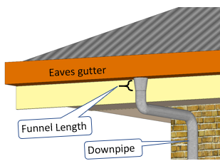
- This program does not calculate the vertical downpipe size. The size calculated coming from a DP, is the size of the underground (or graded) pipe. The downpipe must be calculated in one of the other relevant calculators. If this size is bigger than the "graded" pipe, you must increase all smaller downstream pipes to the calculated downpipe size, or use a funnel section, of the length given in the program, to reduce the DP size.
The program generally conforms to the method outlined in the Australian Plumbing Code AS/NZS 3500.3:2018.
However it differs in the following manner.:-
The code calculates the total equivalent Impervious area draining to each pipe section, then uses a suitable ARI from Table 5.4.3 to calculate the design flow for all pipes .
(The equivalent impervious area of each catchment is its area multiplied by its coefficient of runoff).
This could mean that box gutters designed for a storm return period of 100 years are draining into pipes of a storm return period of 10 years.
Although this may sound strange, it would be very unusual to have two different storm intensities occurring at once on a small building site. So a suitable storm intensity for all pipes must be chosen, normally around 1 in 10 years, if no damage is likely to occur.
 If a storm is greater than the pipeline design storm, there will be a surcharge, and maybe some ponding somewhere.
This must be allowed for in the design. Usually with an overland flow path.
If a storm is greater than the pipeline design storm, there will be a surcharge, and maybe some ponding somewhere.
This must be allowed for in the design. Usually with an overland flow path.However it could also lead to the case of having large pipes from the roof draining into smaller underground pipes, which is not allowed.
So to make life easier, and avoid such problems, this program calculates the runoff from each catchment for the required storm, then sums the runoff (not the equivalent impervious area) into each pipe section. Hopefully this minimises the possibility of larger pipes into smaller pipes, and reduces overflowing during larger storms.
But it does mean that the design will have a slightly longer ARI than the Code requirement.
Which is a good thing.
You might think that this will produce larger pipe sizes, well this is not necessarily the case. Pipes do not come in increments of 1mm dia, so a design requiring a 101mm pipe (say) will require the next larger pipe size, which is 150mm dia.
A 150 dia pipe has a capacity of about 3 times the capacity of a 100mm pipe. So if our pipe is upgraded from a 100 to a 110 dia pipe, it will still result in a 150 dia pipe.
Rainfall
Allowable intensities as per Australian Plumbing Code:-

- Box gutters : ARI 100, for 5 mins (NZ ARI 50, 10 mins)
- Eaves gutters : ARI 20, for 5 mins (NZ ARI 10, 10 mins)
- Pervious, Surface (dwellings) ARI 10, for 5 mins (NZ ARI 10, 10 mins)
- Surface no danger of damage: ARI 2 for 5 mins (NZ ARI 10, 10 mins)
- International, and Uniform Plumbing Code ARI 100,1hr all catchments)
- ARI: Average recurrence Interval
- C: Coefficient of runoff
C - Impervious surfaces : 0.9
C - Pervious Surfaces : 0.3 - 0.8
Default C: 0.8 (User can modify)
C - Pervious Surfaces : 0.3 - 0.8
Default C: 0.8 (User can modify)
If you wish to take advantage of these smaller allowable Intensities for places not listed in the program, or you wish to learn more about ARI's and the new term AEP's then
Using the Program:
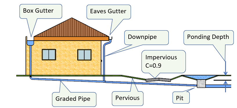
- Draw a plan showing all Catchment areas and pipelines. Example.
- Calculate the area of all catchments entering the pipe system. (don't forget external catchments)
- Give all Catchment areas a number.
- Give all pipe junctions and entry points a letter. (If you run out of alphabet, start doubling up eg aa, ab, ac etc)
- Select a location, or enter your own intensities in the relevant ARI boxes. Learn More
- Enter Catchment Areas
- Choose a Catchment Type. This will automatically select the right intensity, coefficient of runoff, then calculate the flow. For pervious Catchments, the user can modify the coefficient of runoff if required.
- Enter the upstream (U/S) points of each pipe section in the pipeline table.(can be Numbers or letters)
- Enter the Downstream (D/S) point of each pipe section (can be only letters, as a pipe can't drain to a catchment)
- To avoid confusion, everything entered in the U/s or D/s columns will appear in UPPERCASE, regardless of the setting of the "capslock" key.
- Re-entering certain crucial items will remove all calculation results depending on that item. This is so that you are forced to press a recalculate button, and not accidentally accept the previous calculations.
- If catchments drain to a DP, give the DP the same number as the catchment. If catchments drain to a pit, field inlet, RWO or similar, give the pit a name starting with a letter and ending with a number. This helps to alert the program to allow a 20mm fall (Code requirement) through the pit if there is any incoming pipes.
- Press one of the calculate buttons and that's it. This will also commit your entries to memory, allowing you to navigate away from the page and not loose your entries. Conversely, if you make a mistake entering something, which has deleted something else, just refresh the page before pressing any submit buttons.
The pipeline sections can be entered in any order, for instance the main line can be entered first, then all the branches, or you can stop at each junction and enter the branch. As long as all the catchments enter the pipe system, and all the pipe sections connect to each other, with ultimately only one outlet.
It is important to give the catchment areas numbers and the junctions (nodes) letters. This enables the program to differentiate between the two.
A catchment draining directly to a field inlet (gully pit, junction pit, RWO etc) does not have an associated pipe. Whereas a downpipe draining to a field inlet does have a pipe. To avoid confusion as to what is a catchment area and what is a downpipe, the program will determine any non existent pipes and mark as such.
When determining invert levels however, everything will still work out, because the nonexistent pipe will not have a length, or an upstream IL, so nothing will appear in the IL box.
For a large project its surprisingly easy to stuff it up at this stage; but don't worry, the program is keeping an eye out for such things, and will hopefully tell you what went wrong and how to fix it.
Catchment Types
Selecting the 'catchment type' will automatically allot the correct rainfall intensity and coefficient of Runoff.
Each 'catchment type' has a different allowable rainfall intensity, which relates to the severity of damage should a problem occur.
So a box gutter has the highest intensity, ARI 100, 1% AEP, and 'no damage' has the lowest, ARI2 50%AEP
A 'no damage ' catchment (ARI2 is one that probably doesn't need a drain at all, but a drain is put in so that water doesn't flow across a walkway or driveway etc. If all drains to this area are completely blocked, water will overflow to a point of lawful discharge without damage.
For all impervious catchments other than roofs, (concrete, tiles, bitumen areas etc) the coefficient of runoff is 0.9 ARI 10 (clause 5.4.6(a)(ii)).
'Box G ' stands for box gutter and 'Eaves G ' stands for Eaves gutter.
Pervious surfaces include grass, rocks, gravel, sand, etc. (ARI 10) The coefficient of runoff can vary markedly for these areas. The program default is 0.8. However the user can change this to anything (except greater than 1). The figure of 0.8 is high in the scheme of things, but will allow for all those concrete paths, and roadways to be included in the catchment. Also the figure is still a best guess. However the user can lower this, for say large sandy areas, to see if it makes much difference to the pipe sizes.
Other surface catchment types include ARI 20 if water is likely to pond around footings, and ARI 100 if water is likely to run into the building. This can occur if there is a sunken courtyard somewhere. However to be safe, the ARI 100 pipework should extend to a suitable surcharge pit, or discharge point. The surface level of which should be lower than the input SL of the ARI 100 catchment.
The catchment type "given PipeFlow ", or "given flowDP ", allows to accept the flow from another complete pipe network. One pipe network is draining into the next.
The "given PipeFlow" accepts the total flow from another area, eg another building. Whereas the "given flowDP" accepts the flow from a high level DP system, as in joining all DP's at high level into a common downpipe. This will then calculate the minimum size for a vertical DP carrying that flow. It is not affected by the grade of the receiving pipe
Whereas the "given PipeFlow" pipe size is calculated on the grade of the receiving pipe.
More detail on this below.
Refer to "Connecting downpipes at high level"
How to enter a given overland flow into a pit
A "given" overland flow is equivalent to the resultant runoff from a catchment area.
Therefore we must find the area that will give this "given" flow.
The equation for runoff is:-
| flow(L/s) | = | coeff of Runoff * Intensity(mm/hr) * Area(sqm) / 3600 |
| Q | = | CIA/3600 |
| therefore A | = | (Q*3600) / (C*Int) |
| So if we make C | = | 1 |
| Catchment Area (A) | = | given flow(Q)*3600 / Intensity(I) |
| Area | = | Q*3600/Int |
The easiest way to do this is, choose your location to get the intensities, and use the ARI 20 intensity,
substitute this value in the above equation ...1.
And in the catchment table, use catchment type "ARI 20", and make C = 1, and enter the calculated area.
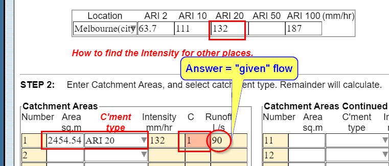
Example
Lets say your "given" flow is 90 L/s, and the location is Melbourne where ARI 20 is 132 mm/hr
Then the required catchment area will be:-
| Area | = | 90 * 3600/132 |
| = | 2454.54 sqm. |
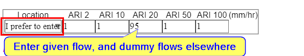
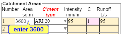
Entering a given overland Flow for only one pipeline
If you only have one pipeline here is another way to enter the given overland flow to find the pipe and pit size.
In the rainfall table select "I prefer to enter a known intensity", and enter the given flow in the ARI 20 column, and in the catchment table enter 3600 in the area column, and 1 in the coefficient of runoff.
So when the program uses the Flow equation it will look like this:- Q = 1 * given flow * 3600 / 3600
Therefore Q = given flow.
BTW this method can be used to enter a given flow in any of the other programs.
Pipe Sizes:
The program will calculate the flow in each pipe section, and the required theoretical pipe size, using the minimum allowable grade for that pipe diameter. Learn more. If there is no available pipe of that exact diameter, the program selects the nearest available larger pipe and displays the nominal diameter (DN). It also shows the capacity of that pipe at the entered grade, and the velocity when flowing full with the 'design' flow.
The program uses the Colebrook-White formula with roughness coefficient "k" = 0.015 as per the Code.
This is only suitable for smooth bore pipes as in plastic, copper or stainless steel.
If the calculated flow requires a pipe larger that 600 mm dia. then the theoretical pipe size is displayed, It is then up to the user to find the nearest available suitable size.
Pipe sizes will not go below 90mm, as this is considered the minimum for storm water drainage for building sites.
If the pipe capacity is much greater than the design flow, meaning the theoretical pipe size is much smaller, then steepening the grade a bit may be just enough to reduce the pipe size.
However no downstream pipe can be smaller than an upstream pipe (for blockage reasons). If this situation is detected the program will upgrade the downstream pipe to the largest upstream pipe.
The program will tell you if this situation exists by highlighting the offending pipes in dark pink, like so,

If you have to use a number of smaller pipes to enter a kerb, do this in a grated pit, situated so that any blockages can flow out of the top of the pit without causing damage. Do not use manifolds, junctions, etc.
 Down Pipes:
 This program does not calculate the size of vertical pipes.
The downpipe size must be calculated in one of the other programs.
However, the graded pipe from the DP, will be sized no smaller than the recommended minimum vertical pipe dia. More info on vertical pipe diameters.
This means that if the DP is larger than the graded pipe, the size can be reduced by the use of a funnel section. The length of this transition section, is dependent on the water depth required to push the required flow into the smaller pipe. This length is given in the program.
Box culverts and rectangular pipes can also be calculated. This is done using the Hazen Williams formula with a coefficient of friction suitable for concrete pipes (140).
There is also the capability of using more than one pipe. This is usually necessary when draining large areas to the kerb and channel, where the outlet pipe is 150mm or 225mm and the pipe diameter into the kerb is limited to 100mm or less (usually).
In this case we could split the flow (in an access chamber) into a number of pipes. Galvanised steel RHS are usually good.
Some local Authorities limit the number of pipes to 3 in any one location. (Locations separated by 6m). Other Authorities limit the flow, or the velocity, at any one point into the kerb.
This is required so that water doesn't overshoot the gutter and flow across the road, being a hazard to traffic.
Please check for your Local Authorities requirements.
Calculating Invert Levels (IL):
Should you wish to do this, the surface level and length of each pipe section must be entered where the program requests it. And elsewhere if there is a change in surface grade that could effect the pipe cover, or pipe grade.
The program can allot a default cover requirement for all pipelines, or the user can allot individual cover requirements.
The lowest invert level draining to each point is calculated. If there is no change in pipe size upstream to downstream, this invert level becomes the next downstream pipeline's upstream invert level, unless there is a pit at this point. In which case a 20mm fall is given across the Pit as required under the Code.
If there is a change in pipe size, ie the D/S pipeline is larger, then the obvert levels are lined up, and the invert level drops by the difference in pipe diameters. The obvert level is the level of the inside top of the pipe.
The reason for this, is that the obvert is where the water level is when the pipe is full. so to avoid raising the water level during a pipe size change, it is best to lower the IL.
Finally, the program will check that the invert level of the outlet pipe is equal to, or above the proposed point of discharge, and all pipes have the required amount of cover. If the pipe grade has to be steepened from the minimum, to achieve this, this will be highlighted with a dark pink background like so,
Grades:
The program calculates pipe sizes using the minimum grade for that pipe diameter. This is suitable for flat sites. However if you have a sloping site, it is best to calculate the grade of the surface between each pipe section, and use that in the table. This will give more economical pipe sizes, and will also give invert levels that will help to keep the pipe underground.
Also if a grade is entered that is flatter than the allowable, the program will change it back to the allowable minimum.
Any grades that have been made steeper than the minimum allowable, are highlighted in pink like so
This can occur through user input, or by the program when calculating invert levels, or various trials where the grade is kept from the last calculation. To get the minimum grade back, delete the pink one and recalculate.
Velocity:
To limit energy losses, the Code suggests a maximum velocity of 1.5 m/s out of pits, and a maximum of 2 m/s elsewhere.
The flow velocity is calculated using the full pipe diameter at the design flow.
If the velocity exceeds 2m/s (or 1.5m/s from Pits) , the pipe size is increased until the velocity falls below the required maximum.
This is again shown with a dark pink background
Ponding depth, Grate, and Pit sizes.:
Choose a suitable ponding depth. If the inlet is in a walkway, the acceptable ponding depth may be only a few mm. If in a grassed area or roadway, the ponding depth may be calculated from the surrounding surface levels.
The top water level should be at least 300mm below any finished floor level.
The program calculates the length of one side of a square inlet grate from three different equations, and displays the largest result. All the equations allow for 50% blockage.
1. From AS/NZS 3500/3:2018 eqn 5.4.10.1
2. The Qld Urban drainage Manual eqn 7.4 (weir conditions)
3. The Qld Urban drainage Manual eqn 7.5 (orifice conditions)
The biggest size is shown.
If the answer is shown with '_P' this means that the Perimeter is significant, and the weir formula was used. So if you want to make a different shape opening, the perimeter/circumference must be used. (grate side * 4)
If the answer is shown with '_A' this means that the Area is significant, and the orifice formula was used. So if you want to make a different shape opening, the area must be used. (grade side * grate side)
It sounds counter intuitive, but for a given PipeFlow and weir length (or orifice dia), there is a certain depth of water required to pass that flow. If this depth of water is reduced, a longer weir length (or greater orifice dia) is required to pass the same flow. Therefore, reducing the ponding depth will increase the required grate or orifice size, and visa versa.
Sometimes greater ponding depths will give ridiculously small grate sizes. Don't use anything less than 100 or 150 dia rain water outlet.
Conversely, sometimes small ponding depths can give ridiculously large grate sizes, which in turn require ridiculously large Pit sizes.
If either of these problems occur, the program will highlight in pink, for change to the default size, or in red for a serious change in the default size.
If you want to make this an access pit, don't go less than 450 sq.
Number of Catchments, or Pipe lengths
There is no limit to the number of catchments, or pipelines that can be entered. Just press the (+ rows) or the (-Rows) button.
Connecting Downpipes at high level to a common downpipe and entering a given PipeFlow.
This program is designed for graded pipes only. However, the size of the graded pipe from a downpipe, is also the minimum suggested size of a DP draining to that point. The downpipes are sized using one of the other DP sizing programs.
If the DP is sized elsewhere, and it is larger than the graded pipe from this program, it can be reduced in size by using a funnel section. The length of which is given in this program. Otherwise please increase the underground (graded) pipe to the DP size. (A pipe should never be reduced in size down stream). If there is no room to fit a funnel section, just remember to manually upgrade any downstream pipes to this size in the CSV data file.
So, how do we drain all the DP's into a common DP, then drain that into the underground system, (or any other graded system). We treat it as two different networks, the high level system and the underground system. Then drain one into the other.
It works like this:-
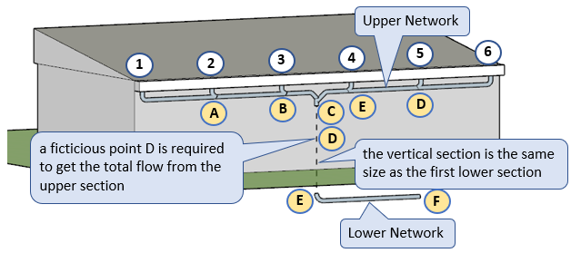
Drain all the upper level pipework to the upper point D as shown above.
Note that all pipes will be at minimum grade, so there is no need to work out the Invert levels.
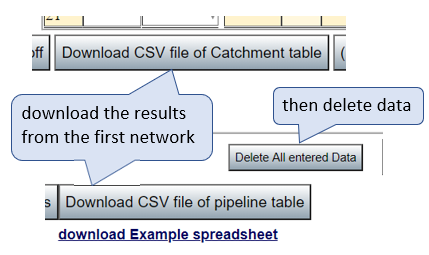
Save this data into a CSV file. This is the first network. Then all the data can be deleted as shown below, ready for the second network to be entered.
Save this data into a CSV file. This is the first network. Then all the data can be deleted as shown below, ready for the second network to be entered.
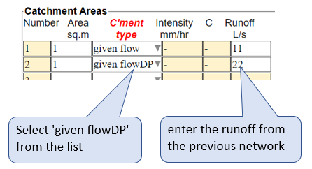
Extra items have been added to the drop down catchment list called "given PipeFlow" and "given flowDP".
Select "given flowDP" indicating to the program to calculate for a vertical pipe.
Selecting "given PipeFlow" indicates to the program to calculate the pipe size depending on the available grade. This is useful if draining a pipe network (or a pipe) from somewhere else on the site. Sometimes on a large site with many buildings, it may be useful to keep all the calculations for each building separate.
There is no need to enter an area, as the program will enter an area of "1" to avoid the 'divide by zero' problem.
Carry on numbering the graded system.
Start the second network by entering the given flowDP into point C, (not point D, as point D is used only to sum all the flows into one point.)
The size of the vertical DP (C to E) connecting the two systems will be calculated to be the minimum size of a vertical pipe that won't become siphonic, or cause vibration, or pressure problems. This pipe will flow only 1/4 to 1/3 full. For more info on vertical pipes refer to the blog "How to calculate the capacity of a vertical Down Pipe".
This method can be used for connecting any two systems. It could be used to connect the flow from another building for instance, by using "given PipeFlow" instead of "given flowDP". In a large job it may be advantageous to keep the design of each building separate.
Exporting to a CSV file:
Both the catchment table, and the pipeline table, can be exported to a CSV file.
This file can be imported into a spread sheet to manipulate and use as you require.
A spreadsheet template is available for download to help with this.
Because this template uses macros to do the intense calculations required, your spreadsheet program may require you to put this file into a "trusted" folder. However the template does not do anything other than the necessary calculations to produce a longitudinal section of the pipework. So it is quite safe, no need to stop coal mining, but you can plant some more trees if you like.
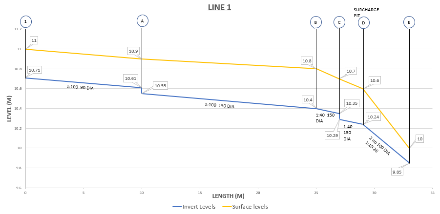
This template will also produce a basic elevation of the pipe system. With a few additions you can produce a diagram as shown below.
It is always a good idea to check the pipework elevations. This gives a visual representation of the results, and can help to identify if anything has gone wrong.
Overland flow path:
Also, should you wish to design an overland flow path, or put all this water into an open channel, this can be done here.
Disclaimer
It is the users responsibility to ensure that all data is entered correctly, and the program is suitable for the purpose intended, and the results have been checked against particular site conditions.
Further Notes and Instructions.
Contact
If you find that the programs save you heaps of agro, please feel free to buy me a few beers.