
When designing Box Gutters, the graphs in the Plumbing Code only allow for designs between the flows of 3L/s and 16L/s.
With industrial buildings getting much bigger, there is a need to go well outside these limits.
I will now show you how to do this by using the graphs, and associated figures from the Plumbing Code AS/NZS 3500.3 2018
Step one: pick any size box gutter that fits on the relevant graph, and determine the depth, and the rain water head sizes.
Step two: Calculate the necessary scaling factors to scale these dimensions to the flow we want.
However its not quite that easy. Scaling one dimension does not necessarily result in scaling another by the same amount.
For example, scaling the sides of a square by a factor of two, increases the area by a factor of 4.
Fluids are a bit like that. However there are things that can’t be scaled, like gravity, viscosity, surface tension, friction etc.
So how do we find out the resultant scaling factor?
We start by finding an equation relevant to the situation that has all the related variables.
For box gutter depth, any equation incorporating flow, depth and width will do.
The best and simplest is the critical depth equation.
Critical depth occurs near the outfall of every box gutter.
The usual nomenclature applies Q = flow, W = width, Y = depth. Suffix 1 represents the base condition to be scaled, and suffix 2 the scaled result.
Critical depth formula
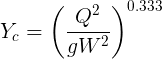
Constants have a scale factor of 1, therefore they are not required, so we can eliminate “g”.
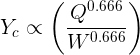
We then say that Yc is proportional to:-
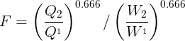
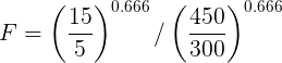
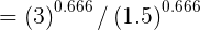
We now find the scale ratio between Q1 & Q2 and W1 & W2 and the resulting multiplying factor F:-
By the way, the slope also can’t be scaled, so the slope must be the same for both gutters.
Try an example
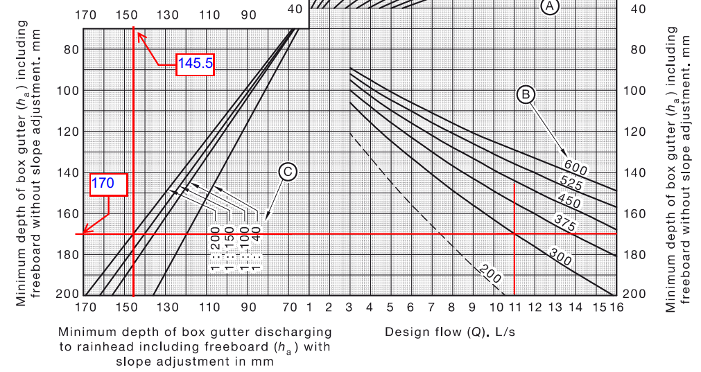
Assume our base gutter has Q1 = 5L/s, W1= 300, slope = 1:200, from Code fig I1 BGD1 = 110mm
Lets check for a new gutter with Q2=15L/s, W2 = 450, (any suitable width can be used), slope = 1:200. Multiplying factor:-

However a box gutter has a freeboard which we do not want to scale, So we take this value off the original BG depth, and add it back to the new BG depth
So new BG depth =((orig depth – freeboard) x F ) + freeboard ………..(1)
= ((110 – 58) x 1.587) + 58
= 140
= Code Depth from fig I1 (for BG Q = 15 L/s, W = 450.)
How to find the freeboard
From fig I1 look up the BG depth for both gutters, and substitute in equation 1 above.
140 = ((110 – fb) x 1.587 ) + fb. solving, fb = 58mm
This does assume the new gutter depth will be the same as the code. However checking with all other Box Gutter combinations gives the same result.
So this value works in all situations.
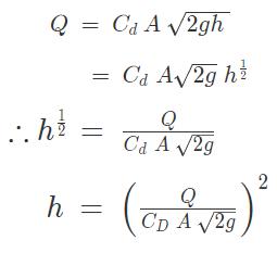
RWH depth, scaling factor
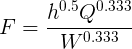
Similarly we can find the scaling factor for the RWH depth from the orifice formula
Cd= Coefficient of Discharge (constant)
A = Area
h = height of water over.
g = acceleration due to gravity (constant)
constants do not require scaling
Therefore are not required in the scaling factor F
…….(2)
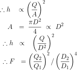
Therefore height (ie depth of RWH) is proportional to (Q/A)2
π and 4 are constants, so can be removed
Therefore A is proportional to D2
Substitute D2 for A in eqn 2
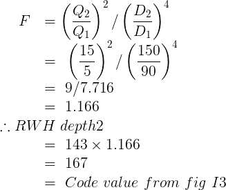
Multiplying Factor F
Example RWH depth scaling
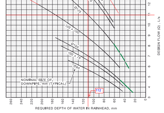
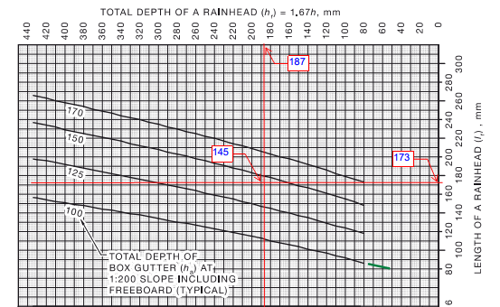
Base Gutter as before Q1 = 5L/s, W1= 300, slope = 1:200, DP1 dia = 90, from Code fig I1 BGD1 = 110mm, from fig I3 RWH1 depth = 143 RWH1 length = 119
New gutter Q2 = 15 L/s W2 = 450 DP2 = 150 (any suitable width and DP can be assumed)
However from Code note 1 fig I2 the RWH depth should be >= to DP dia x 1.25
Therefore RWH depth = 150 x 1.25 = 188 mm.
But this value does not show up on the graph. So for the purpose of the exercise we shall stick to the graph value of 167.
Because the RWH length depends on the RWH depth, Increasing the depth also increases the length, meaning that we won’t be able to check the result with the graph if we don’t use the graph calculated depth.
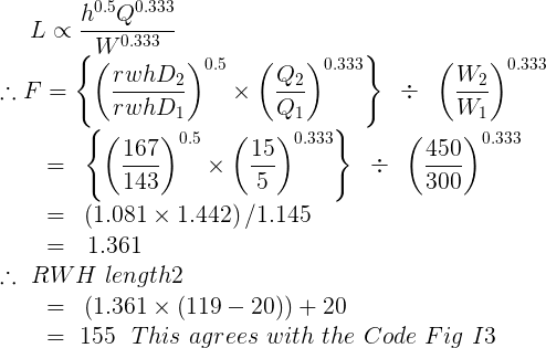
RWH Length, scaling factor
Similarly we can find the scaling factor for the RWH length from the trajectory formula.
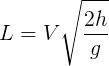
Substitute for V with V=Q/A
Substitute for A with the critical depth formula. A = W x Yc This gives:-
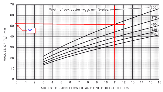
The RWH length also involves a clearance of 20.
h = RWH depth
So the new length = F x (RWH length1 – 20) + 20
Example RWH length scaling
Base Gutter as before Q1 = 5L/s, W1= 300, slope = 1:200, DP1 dia = 90, from Code fig I1 BGD1 = 110mm, from fig I3 RWH1 depth = 143 RWH1 length = 119
New gutter Q2 = 15 L/s W2 = 450 DP2 = 150 (any suitable width and DP can be assumed)
Using this method, the Box Gutter sizes for 150 L/s, width = 600, DP dia = 375, are as follows:-
Box gutter depth = 372
Box gutter width = 600
RWH depth = 433
RWH Length = 470
But is this correct?

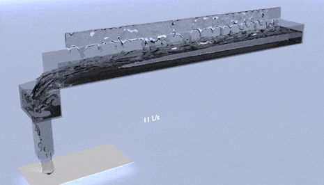
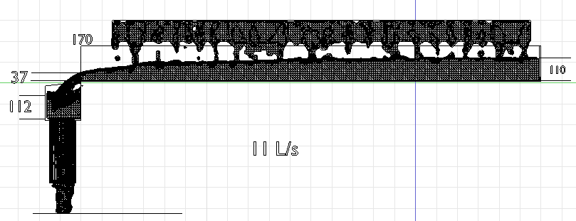
Failing a full size test, the next best thing is Computational Fluid Dynamics. (CFD)
The simulation at the top of the page was done using these dimensions, and the flow was checked by measuring the depth at the brink.
The depth at the brink of a free outfall from a gutter = 0.7 x critical depth.
As can be seen from the simulations, there is no overflowing so the gutter works.
Compare to CSIRO formulas
K.G. Martin from the CSIRO developed formulas for roof gutter design over 40 years ago.
This is what we used before the Plumbing Code was invented.
Assuming the laws of physics haven’t changed, these formulas should still give an acceptable result
So how do they compare:-
Box gutter depth = 377 = 5mm deeper
Rain water head depth = 494 = 61mm deeper
Rain water head length = 554 = 84mm deeper.
All figures are bigger so the gutter will still work.
The box gutter depth is within an acceptable difference.
The RWH though is deeper than would be expected. Why is this?
The CSIRO formulas for the RWH depth use both the weir and the orifice formula.
The weir formula being used when the depth of water in the RWH < 1/3 DP dia.
The weir formula gives a greater depth in this situation.
The plumbing Code uses only the orifice formula. That is why we must increase the depth to 1.25 x DP dia if the calculated RWH depth < 1.25 x DPdia.
(refer to note1 figure I2) This is the cross over point of the two formulas.
so DP dia x 1.25 = 375 x 1.25 = 469 = 25mm difference. (looking incredibly reasonable)
Using this RWH depth as the new depth in the RWH length scaling factor we get:-
new RWH length = 530 = 60mm longer. (maybe a different clearance was used)
However looking at the simulation, a deeper and longer rain water head may cut down that build up on the far side.
Our gutter works, because there is a lot of tolerance built into a RWH, however to be strictly correct (with the Code) we should make these changes.
Your mission should you choose to accept it
Prove it for yourself by scaling say a 3L/s gutter up to 6, 9, and 12L/s, varying the width in each case.
All these results can be checked with the Code, figure I1 for the gutter depth, and fig I3 for the RWH sizes.
Because we are not working in fractions of a mm, and we are getting results off graphs, there could be rounding errors of a few mm’s.
Free Programs
If you don’t want to fool around with the graphs, you can get accurate interpolated results with these free programs.
However if you go above 16L/s these programs revert to formulas developed by the CSIRO, and require a small charge..
Once you have satisfied yourself that the theory works you can now:-
GO FORTH AND PROSPER


